
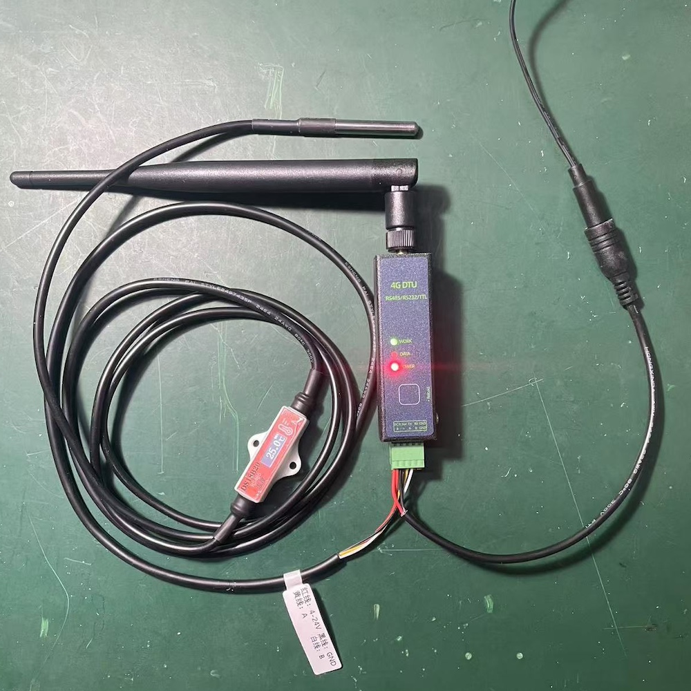
Appearance
Connect a temperature and humidity sensor through a DTU
Connect an RS485 Modbus temperature and humidity sensor to a DTU that supports point configuration. Add the device in the cloud, configure temperature and humidity points, and check live readings and history.
Before you start
- A DTU that can connect to the platform, with its device ID and security code.
- A Modbus RTU temperature and humidity sensor and its register map.
- Power supplies, communication wiring, and site connectivity suitable for the hardware manuals.
- An organization and project with an active plan. Device binding requires the Owner; point configuration requires a Manager or Owner.
Follow the hardware manuals for power and wiring. Disconnect power before connecting RS485 signal wires. Match baud rate, data bits, stop bits, and parity on the sensor and DTU. Give each slave a unique address when several share a bus.
1. Create a project and add the device
Sign in and create a project in the target organization. Open its device list, click Add Device, enter the device ID and security code, and add it to that project.
Open the device details and check whether its last connection time updates. Resolve power or network problems before configuring points if the device has not connected.
2. Prepare the register parameters
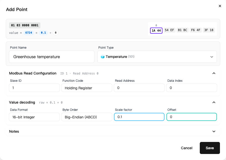
This example uses two adjacent 16-bit registers:
| Parameter | Temperature | Humidity |
|---|---|---|
| Slave ID | 1 | 1 |
| Function code | Holding register (03) | Holding register (03) |
| Read address | 0 | 0 |
| Data index | 0 | 1 |
| Data format | Signed 16-bit integer | Unsigned 16-bit integer |
| Byte order | Big-endian | Big-endian |
| Scale factor | 0.1 | 0.1 |
| Offset | 0 | 0 |
These addresses, formats, and conversions are teaching examples. Use your sensor's register map if humidity is at another address, the function code is 04, or the byte order differs.
3. Add the temperature point
- Open the device's Points, then choose Add Point from the Add Point menu.
- Enter “Greenhouse temperature” and select the Temperature type.
- Expand Modbus Read Configuration and enter the slave ID, function code, address, and index.
- Expand Value decoding and set the format, byte order, scale factor, and offset.
- Save and return to the device overview to check updates.
4. Add the humidity point
Repeat the steps for “Greenhouse humidity,” selecting Humidity and its corresponding format and index. When both points share a slave ID and start address, their indices select different values from the response.
See the Modbus reference for field definitions.
5. Verify the readings
Check temperature, humidity, and update times in the overview. With the example conversion, a raw temperature of 253 displays as 25.3 °C. Compare it with the sensor display or a reference instrument in the same location to detect unit, format, or scaling errors.

Open a point and select a time range to view its history. If live readings exist but history is empty, check the range, debug mode, and historical storage. See View live and historical data.
Once readings are correct, you can set thresholds, create a rule, or set up forwarding.