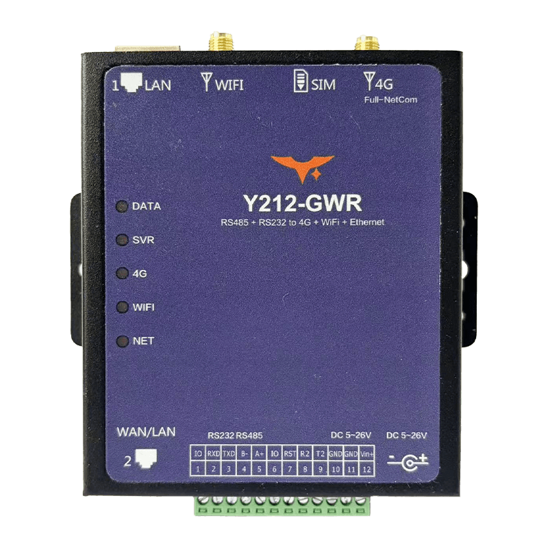
Appearance
Y212-GWR Tri-Mode Serial Gateway Router Specification
Reference: Y212-G / Y212-GWR Technical ManualCountry Coverage: Country Coverage Quick Guide
Contents
- Overview
- Ordering Information
- Key Features
- Technical Specifications
- Interfaces and Pin Definitions
- Mechanical and Environmental
- Installation and Wiring
- Important Notes
1. Overview
Y212-GWR is an industrial serial gateway and router that combines 4G, Wi-Fi, and RJ45 Ethernet in one device. It connects RS232 and RS485 equipment to the cloud while also providing WAN, Wi-Fi STA or AP, and Ethernet routing for high-availability field networks. With automatic uplink failover, remote configuration, OTA, and alarm reporting, it helps keep unmanned sites online with less maintenance effort.
It is a strong fit for PLCs, meters, pumps, environmental stations, energy cabinets, and municipal equipment that need serial access plus backup network paths.
| Item | Description |
|---|---|
| Product Type | Industrial 4G, Wi-Fi, and Ethernet serial gateway router |
| Uplink Options | 4G LTE, Wi-Fi 2.4 GHz, and dual RJ45 Ethernet |
| Device Interfaces | RS232, RS485, dual RJ45, optional TTL secondary UART |
| Link Strategy | Automatic WAN > Wi-Fi > 4G priority switching |
| Power Input | 6 to 26 VDC |
| Typical Use | Redundant uplink, edge routing, and remote maintenance |
Highlights
- Triple-link backup keeps field data online when one path fails
- One unit handles serial conversion, routing, and local Wi-Fi access
- AP and STA modes simplify commissioning and maintenance
- Cloud-side OTA, logs, and alarms reduce service trips
- DIN-rail-ready housing fits industrial cabinets and remote stations
Typical Applications
- Agricultural IoT: Remote control and data aggregation for greenhouses, livestock sites, and pumps
- Energy and municipal systems: Remote monitoring for distribution switches, street lights, and water pipelines
- Industrial automation: Connect PLCs and meters to cloud platforms through serial or Ethernet interfaces
- Environmental protection: Multi-link protection for air, water, and noise monitoring stations
2. Ordering Information
2.1 Model Naming
text
Y212 - G W R
  |       | | \- R: RJ45 Ethernet port, WAN / LAN
  |       | \--- W: Wi-Fi 802.11 b/g/n, AP / STA
  |       \----- G: 4G LTE cellular, Qualcomm Cat.4 on the current Y212-GWR
  \------------- Y212: Y2 series multi-mode serial data terminal
2.2 SKU and Network Capability
| SKU | Chipset / Mode | 4G Bands | Wi-Fi | RJ45 | Power |
|---|---|---|---|---|---|
| Y212-GWR | Qualcomm Cat.4 router gateway, RS232 + RS485 + dual RJ45 + Wi-Fi | 7 modes / 15 bands: GSM EGSM900/DCS1800; WCDMA B1/B8; CDMA2000 BC0; TD-SCDMA B34/B39; LTE-FDD B1/B3/B5/B8; LTE-TDD B34/B38/B39/B40/B41 | 802.11 b/g/n, AP or STA | Port 1 fixed LAN; port 2 WAN by default and configurable to LAN | 6 to 26 VDC, typical 12 V / 2 A |
2.3 Package Contents
- Y212-GWR main unit x1
- 4G omnidirectional antenna, SMA x1
- Wi-Fi antenna, SMA x1
- DC power terminal and
5.5 x 2.1 mmadapter socket x1 - SIM eject pin, quick-start card, warranty card
2.4 Optional Accessories
- DIN-rail mounting kit
- USB-to-RS485 / RS232 debug cable
12/24 VDCindustrial power supply, surge protector, shielded Ethernet cable
2.5 Country Support Quick Guide (Current Cat.4 Version)
This model supports the following cellular bands:
- GSM: EGSM900 / DCS1800
- WCDMA: B1 / B8
- CDMA2000/EVDO: BC0
- TD-SCDMA: B34 / B39
- LTE-FDD: B1 / B3 / B5 / B8
- LTE-TDD: B34 / B38 / B39 / B40 / B41
Use the table below to quickly decide whether this hardware is a fit for your deployment country:
| Country or Region | Decision | Typical Band Match Summary |
|---|---|---|
| China Mainland | Supported | Strong overlap with LTE FDD B1/B3/B5/B8 and LTE TDD B34/B38/B39/B40/B41 |
| India | Supported | Common LTE bands B1/B3/B5/B8/B40/B41 have strong overlap |
| Thailand, Vietnam, Indonesia, Malaysia, Philippines, Singapore | Supported in most areas | Main LTE deployments often include B1/B3/B5/B8; check carrier by site |
| Japan, South Korea | Partially Supported | Partial overlap (mainly B1/B3/B5), but some operator primary bands are outside this model |
| EU and UK (Germany, France, UK, Italy, Spain, Netherlands, Poland) | Partially Supported | Overlap on B1/B3/B8; missing common low bands such as B20/B28 in many networks |
| Australia, New Zealand | Partially Supported | Overlap exists, but missing B28 can reduce rural or indoor coverage |
| United States, Canada | Not Recommended | Key local LTE bands used by major operators are not sufficiently covered |
Important: This is a band-overlap reference, not a carrier guarantee. Actual availability depends on local operator network planning, IoT SIM profile, APN, and certification requirements. Fallback note: 2G/3G fallback works only where local 2G/3G service is still active.
3. Key Features
- 4G + Wi-Fi + Ethernet Backup: Three uplink options switch automatically to keep communication online.
- Serial and IP in One Device: RS232, RS485, and dual RJ45 support mixed legacy and IP deployments.
- Wi-Fi AP and STA: Join an existing WLAN or create a hotspot for local setup and service.
- Cloud-Ready Protocols: Supports TCP, UDP, HTTP, HTTPS, MQTT, MQTTS, and WebSocket.
- Remote OTA and Diagnostics: Manage parameters, logs, alarms, and upgrades from the cloud.
- Industrial Power and Protection:
6 to 26 VDCinput with surge, reverse-polarity, and watchdog protection. - Flexible Local Expansion:
2 xconfigurable IO plus1 xfunction pin and optional TTL UART support local integration. - DIN-Rail Friendly Design: Compact housing speeds up installation in gateways, cabinets, and stations.
4. Technical Specifications
4.1 Network and Wireless
| Parameter | Specification |
|---|---|
| 4G Mode | Qualcomm Cat.4 with 2G / 3G fallback |
| 4G Bands | 7 modes / 15 bands: GSM EGSM900/DCS1800; WCDMA B1/B8; CDMA2000 BC0; TD-SCDMA B34/B39; LTE-FDD B1/B3/B5/B8; LTE-TDD B34/B38/B39/B40/B41 |
| Wi-Fi | IEEE 802.11 b/g/n, 2.4 GHz, switchable AP and STA modes |
| Ethernet | 2 x RJ45, 10/100 Mbps; port 1 is fixed LAN and port 2 defaults to WAN, configurable to LAN by command |
| Access Path | Smart switching from WAN to Wi-Fi to 4G, queryable through AT*CNWK |
4.2 Communication Interfaces
| Parameter | Specification |
|---|---|
| Main Serial Port | RS232 + RS485, 1200 to 500000 bps, default 9600-8-N-1 |
| Secondary UART | TTL 3.3 V / 5 V, RX2 and TX2 on some versions |
| Digital IO | IO1 / IO2 configurable as input or output, plus 1 x function pin IO3, 3.3 V high level |
| Command Access | AT commands can be sent through serial, LAN, Wi-Fi, or remote 4G path |
4.3 Electrical and Power Consumption
| Parameter | Specification |
|---|---|
| Power Input | 6 to 26 VDC, recommended 12 V / 2 A; peak current 1 to 2 A |
| Power Interface | Pluggable terminal and 5.5 x 2.1 mm DC jack |
| Typical Consumption | 100 to 200 mA @ 12 V standby; 200 to 300 mA during 4G transmission; slightly higher with concurrent Wi-Fi and 4G |
| Protection | Reverse-polarity, over-voltage, surge protection, and multiple hardware watchdog stages |
4.4 Environmental and Reliability
| Parameter | Specification |
|---|---|
| Operating Temperature | -40 to 85 C |
| Humidity | 5 to 95% RH, non-condensing |
| Storage Temperature | -45 to 90 C |
| MTBF | > 200,000 h, typical |
4.5 Wi-Fi and RJ45 Operating Modes
| Module | Mode | Description |
|---|---|---|
| Wi-Fi | STA | Joins an existing hotspot to reach the WAN; Wi-Fi LED stays on |
| Wi-Fi | AP | Provides a local hotspot; Wi-Fi LED blinks 1 s on / 2 s off |
| RJ45 | LAN | Connects downstream terminals or a PC; default subnet 192.168.77.1 |
| RJ45 | WAN | Connects upstream router or core network; supports static IP or DHCP |
5. Interfaces and Pin Definitions
5.1 12-Pin Terminal Definition
| Pin | Signal | Description |
|---|---|---|
| 1 | IO1 | Configurable digital input or output, 3.3 V high level |
| 2 | 232-RX | RS232 receive, connect to external TX |
| 3 | 232-TX | RS232 transmit, connect to external RX |
| 4 | 485B- | RS485 differential B- |
| 5 | 485A+ | RS485 differential A+ |
| 6 | IO2 | Configurable digital input or output |
| 7 | IO3 | Extended IO or function pin |
| 8 | RX-TTL | Secondary UART RX2, optional |
| 9 | TX-TTL | Secondary UART TX2, optional |
| 10 | GND | Ground |
| 11 | GND | Ground, paralleled with pin 10 |
| 12 | Vin+ | DC positive input, 6 to 26 V |
5.2 Interface Summary
| Interface | Description |
|---|---|
| SMA Connectors | Separate ports for 4G and Wi-Fi, 50 ohm impedance |
| SIM Slot | Drawer-style full-size SIM, yellow push button, supports SIM and USIM |
| Reset Button | Press 3 to 5 s for soft reset, >10 s for factory reset |
| LEDs | DATA, Server, 4G, Wi-Fi, and Network indicators |
| RJ45-1 | Fixed as LAN |
| RJ45-2 | Defaults to WAN, configurable as LAN |
5.3 LED Status
| LED | Status | Meaning |
|---|---|---|
| DATA | On | Network data TX/RX active |
| Server | On | Connected to center server |
| 4G | On | Currently online through 4G; 1 s on / 1 s off means searching |
| Wi-Fi | On | Wi-Fi connected in STA mode; 1 s on / 1 s off means searching; 1 s on / 2 s off means AP mode |
| Network | 1 s on / 1 s off | Searching wired network |
| Network | 64 ms on / 3 s off | Not registered to a network |
| Network | 64 ms on / 1 s off | Registered to a network but not connected to the server |
| Network | 64 ms on / 300 ms off | Data link established |
6. Mechanical and Environmental
| Item | Specification |
|---|---|
| Housing Material | Metal or ABS DIN-rail housing, UL94 V-0 flame retardant |
| Dimensions | 105.4 x 98 x 25 mm |
| Mounting | 35 mm DIN rail, panel screws, or desktop placement |
| Weight | About 220 g, including antenna and terminal |
| Protection Rating | IP20, indoor use |
| Cooling Clearance | Recommended top and bottom >=15 mm, left and right >=10 mm |
7. Installation and Wiring
- Connect the antennas: Match the 4G and Wi-Fi antennas to the labeled connectors, keep them vertical, and ensure good grounding.
- Insert the SIM card: Press the side eject button, place an activated IoT SIM into the tray, and reinsert it securely.
- Wire the power input: Use
14 to 24 AWGwire to connect GND and Vin+, or use a5.5 x 2.1 mmDC plug. Verify polarity and voltage before powering on. - Configure the Ethernet ports: Use port 1 as LAN. Use port 2 as WAN by default, or switch port 2 to LAN for pure local-network deployments.
- Connect the serial ports: Use RS232 or RS485 for field devices with shielded twisted pair and proper grounding. The TTL secondary UART can be used for MCU debugging.
- Configure Wi-Fi: Set SSID and password through the configuration tool or
AT*WSET. AP mode can be enabled for local hotspot access. - Power on and commission: Observe all five LEDs to confirm the access path, then complete parameter configuration and cloud connectivity testing.
8. Important Notes
- Link Priority: The default priority is
WAN > Wi-Fi > 4G. It can be customized by command. In LAN-only deployments, disable unnecessary uplink paths to avoid loops. - Power and Grounding: Use an independent DC power supply and add a
2 Afast fuse plus surge protection. Bond signal ground and protective earth properly. - Antenna Isolation: Keep the 4G and Wi-Fi antennas separated as much as practical to reduce mutual interference. Add lightning protection for outdoor installations.
- Security Configuration: HTTPS and MQTTS functions must be enabled and managed on the platform side following enterprise security policy.
- Firmware Upgrade: Keep both power and uplink stable during OTA. If an upgrade fails, restore factory settings through the serial interface and reconfigure.