
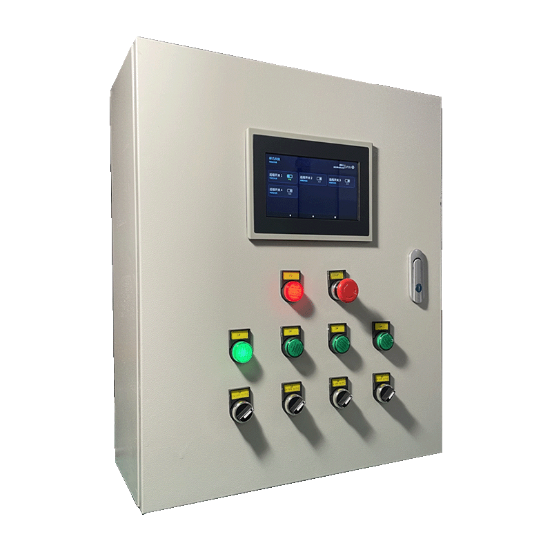
Appearance
Y951 — Smart Remote Control Cabinet Specification
Contents
- Overview
- Ordering Information
- Key Features
- Technical Specifications
- Controls and Operation
- Installation and Safety
- Important Notes
1. Overview
Y951 is the Smart Remote Control Cabinet in the YenGear field-ready power-control range. It provides 2–16 circuits for pumps, fans, aerators, lighting, valves, and other field equipment. The cabinet combines centralized power distribution, per-circuit control, cloud scheduling and linkage, status records, and local manual operation. Network options are 4G, Wi-Fi, and RJ45 Ethernet.
Global power notice: Each cabinet is built for a specific project and destination market. Before ordering or installation, confirm the nominal voltage, frequency, phase and conductor arrangement, earthing system, prospective short-circuit current, and local compliance requirements. The site supply must match the product nameplate, approved wiring diagram, and order confirmation.
Cloud control, scheduling, and linkage require the cabinet to remain online. Actual load-running feedback, electrical monitoring, offline automation, and other non-standard functions require the corresponding project configuration.
Typical applications include aquaculture, livestock farming, greenhouses, pump stations, equipment rooms, and distributed sites.
Product Boundary
| Product | Primary Role |
|---|---|
| Y951 | Internet-connected multi-circuit remote control |
| Y952 | Local temporary-power protection, monitoring, alarms, and event traceability |
| Y953 | One-to-many control through an on-site wireless link |
Select Y951 when personnel need to view, start, stop, or schedule multiple circuits over an internet connection. Select Y952 when local electrical safety and event traceability are primary. Select Y953 when one local control point must operate dispersed nodes without long control cables or an external network.
2. Ordering Information
Model Code
text
Y951-xx-C
  │   │  └── C: Communication (G / W / R)
  │   └───── xx: Number of circuits (2–16)
  └───────── Y951 series
Examples: Y951-4-G is a 4-circuit 4G model; Y951-8-W is an 8-circuit Wi-Fi model.
| Suffix | Communication |
|---|---|
-G | 4G |
-W | Wi-Fi |
-R | RJ45 Ethernet |
Available combinations are subject to order confirmation.
Required Order Information
| Item | Required Details |
|---|---|
| Circuits and Control | Circuit count, independent control, scheduling, linkage, forward/reverse control, interlocking, and offline logic |
| Site Supply | Nominal voltage, frequency, phase/conductors, earthing system, prospective short-circuit current, and incoming protection |
| Loads | Voltage, rated power, starting current, starting method, and load type |
| Network | 4G, Wi-Fi, or RJ45, including coverage or cable routing |
| Options | Monitoring, power/phase-loss alarm, audible/visual alarm, display, GPS, and feedback |
| Enclosure and Market | Material, dimensions, mounting, environment, local codes, certification, marking, and labeling |
Standard supply includes one configured cabinet, product documentation, and warranty documentation. Options are included only when specified in the order.
3. Key Features
2–16independently controlled circuits4G,Wi-Fi, orRJ45connectivity- Remote start/stop, cloud scheduling, and project-configured linkage
- Local manual control, online status, and operation records
- Optional current monitoring, power/phase-loss monitoring, alarms, display, and load feedback
- Configurable load control, enclosure material, dimensions, and mounting
4. Technical Specifications
Electrical and Circuit Parameters
| Parameter | Specification |
|---|---|
| Input Supply | Project-specific AC supply; must match the nameplate and order confirmation |
| Frequency | Confirmed 50Hz or 60Hz; dual-frequency use only when explicitly rated |
| Circuit Count | 2–16 standard circuits |
| Standard Load per Circuit | Reference value 2.2kW; confirm voltage, load type, and starting conditions |
| Higher Loads | Project-specific configuration required |
| Control Voltage | 12~24V DC, depending on the control unit |
| Total Current | Reference configuration 20A; final rating is project-specific |
220Vand380Vare project reference values, not universal input ratings. The delivered cabinet's nameplate and approved documents take precedence.
Communication and Platform
| Parameter | Specification |
|---|---|
| Communication | 4G / Wi-Fi / RJ45 Ethernet |
| Access | YenGear IoT Cloud Platform or mobile app |
| Control | Local manual, remote start/stop, cloud scheduling, and configured linkage |
| Online Requirement | Remote control, scheduling, and cloud linkage require network access |
| Records | Online status, circuit status, and operation records, subject to configuration |
| Upload Interval | Device- and platform-configured; 1h is not a series-wide default |
Optional Protection and Monitoring
| Function | Configuration Boundary |
|---|---|
| Current Monitoring | Range, accuracy, and circuit count depend on the selected module |
| Power/Phase-Loss Monitoring | Detection and alarm logic are project-specific |
| Audible/Visual Alarm and Display | Optional; trigger and reset logic are project-specific |
| Overvoltage/Undervoltage Protection | Thresholds and action time depend on the installed device |
| Short-Circuit Protection | Breaking capacity depends on the installed protection devices |
| Self-Test and Load Feedback | Available only when included in the confirmed configuration |
Protection thresholds, action times, breaking capacity, and monitoring accuracy are defined by the installed components and test documentation.
Enclosure and Dimensions
| Parameter | Specification |
|---|---|
| Standard Material | Galvanized steel sheet |
| Optional Material | Stainless steel |
| Mounting | Wall or pole mounting |
| Operating Temperature | Depends on the enclosure and installed components |
| Dimensions | Depend on circuit count and configuration |
| Circuit Configuration | Reference Dimensions |
|---|---|
| 4 circuits | 400 × 500 × 200mm or 500 × 600 × 200mm |
| 6 circuits | 500 × 600 × 200mm |
| 8 circuits | 600 × 800 × 200mm |
| 16 circuits | 1500 × 700 × 370mm |
Final dimensions and environmental ratings are stated in the approved outline drawing and order documents.
5. Controls and Operation
| Component or Mode | Function |
|---|---|
| Emergency Stop | Cuts the control circuit in an emergency; reset method depends on configuration |
| Run Indicator | Shows the contactor or control-circuit switching state |
| 3-Position Knob | Manual on / manual off / automatic control |
| 4-Position Knob | Manual stop / reverse / forward / automatic control for configured reversing circuits |
| Remote Control | Starts or stops a selected circuit through the platform or app |
| Cloud Scheduling and Linkage | Executes platform-issued schedules or configured data rules while online |
An “On” status indicates the controller or switch state, not confirmed operation of the connected load. Use current monitoring, auxiliary contacts, or other feedback when actual operation must be verified.
6. Installation and Safety
- Mount the cabinet according to the approved outline drawing and site conditions.
- Before installation, verify the site supply, total load, protection coordination, enclosure rating, network conditions, and destination-market requirements.
- Connect circuits only according to the terminal markings and approved wiring diagram.
- Do not energize the cabinet if the supply does not match the nameplate and approved documents.
- Do not perform live wiring or modify internal components, conductor sizes, or wiring without authorization.
- Installation, testing, and maintenance must comply with local electrical codes and be performed by appropriately qualified personnel.
- Before energizing, verify insulation, earthing, phase sequence, protection operation, and start/stop operation for every circuit.
7. Important Notes
- Network Dependency: Standard remote control, scheduling, and cloud linkage require an active network connection. Local manual control remains available when site power is normal.
- Configuration Boundary: Monitoring, protection, alarms, displays, feedback, reversing control, and offline logic are included only when confirmed in the order.
- Load Boundary:
2.2kWper circuit is a reference value. Inductive and high-starting-current loads require verification of voltage, frequency, starting conditions, and protection coordination. - Environmental Boundary: Enclosure rating, material, dimensions, and operating temperature depend on the delivered configuration.
- Document Priority: The nameplate, order confirmation, approved wiring and outline drawings, bill of materials, component documents, test records, and destination-market compliance documents govern the delivered unit and installation.