
Appearance
Y401 / Y402 / Y403 Wireless I/O Modules User Manual
Applicable models: Y401-11-L, Y401-22-L, Y401-44-L, Y402-11-L, Y402-44-L, Y402-4411-L, and Y403-11-L.
Product Introduction
The Y40 Wireless I/O Modules use a private LoRa link to replace long-distance control wiring. Each device provides digital input and relay output terminals, so a switch, sensor contact, PLC relay output, alarm contact, or controller contact can be carried, mapped, or forwarded to a remote relay output without a SIM card, Internet connection, or LoRaWAN gateway.
Main features:
- LoRa wireless communication,
398 to 525 MHz - Up to
10 kmin open areas as a model-, antenna-, and site-dependent planning value 9 to 36V DCpower input- DI supports
passive dry contactandNPN open-collector input - DO uses SPDT relay output, rated
AC 277V / 5AorDC 28V / 5A - DIN rail installation
Control Logic
Y401 Point-to-Point
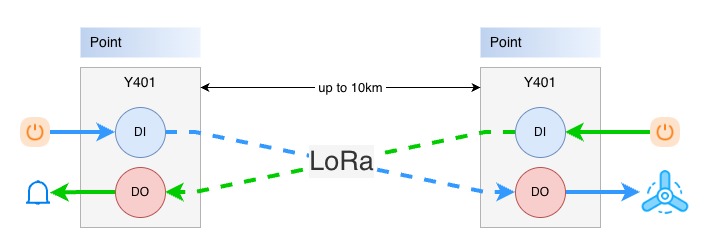
Y401 uses two paired devices: Device A and Device B. When a DI on one device closes, the corresponding DO relay on the other device energizes. When the input opens, the remote relay resets.
Channel mapping:
| Model | Device A Input | Device B Output | Device B Input | Device A Output |
|---|---|---|---|---|
| Y401-11-L | DI1 | DO1 | DI1 | DO1 |
| Y401-22-L | DI1 to DI2 | DO1 to DO2 | DI1 to DI2 | DO1 to DO2 |
| Y401-44-L | DI1 to DI4 | DO1 to DO4 | DI1 to DI4 | DO1 to DO4 |
Y402 One-to-Many
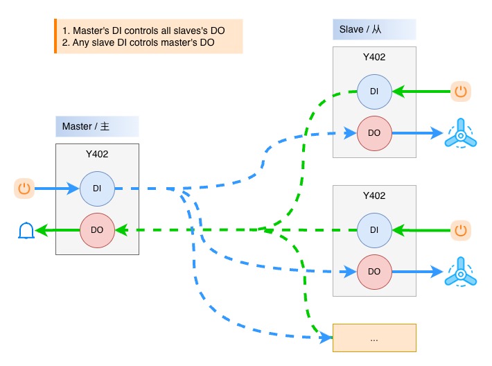
Y402 uses one master and one or more slaves. When the master input closes, the corresponding output on all slaves energizes. When any slave input closes, the corresponding output on the master energizes.
Channel mapping:
| Model | Master to Slave | Slave to Master |
|---|---|---|
| Y402-11-L | Master DI1 -> all Slave DO1 | Any Slave DI1 -> Master DO1 |
| Y402-44-L | Master DI1 to DI4 -> all Slave DO1 to DO4 | Any Slave DI1 to DI4 -> Master DO1 to DO4 |
| Y402-4411-L | Master DI1 -> all Slave DO1 to DO4 | Any Slave DI1 to DI4 -> Master DO1 |
The master output resets only after the corresponding input on all slave devices returns to open.
Y403 Multi-Node Linkage
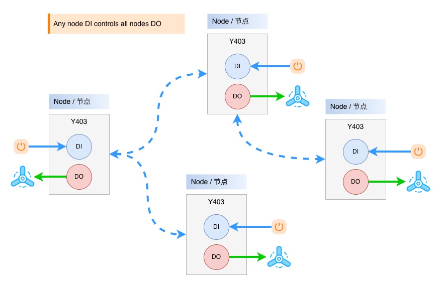
Y403 uses multiple equal-status nodes. When the DI on any node closes, the DO on all nodes energizes, including the local node. The outputs reset only after every node input returns to open. Nodes can automatically relay signals to extend the practical communication path.
Core Application Patterns
| Scenario | Recommended Model | Description |
|---|---|---|
| Access-control signal extension | Y401-11-L / Y401-22-L / Y402-11-L | Carry a door, gate, or barrier contact to a remote relay or controller input without a long signal cable. |
| Multi-point linkage alarm | Y403-11-L | Forward an alarm contact to linked node outputs for coordinated auxiliary annunciation; keep a certified independent path for life-safety functions. |
| Remote wireless equipment control | Y401 / Y402 / Y403 | Carry a local switch or PLC contact to a suitably rated relay, contactor, lamp, valve, or pump control circuit. |
| Multi-channel gate, lighting, or valve control | Y401-44-L / Y402-44-L | Use independent channels for multiple loads or remote stations. |
| One trigger drives multiple actions | Y402-4411-L | Map one master input to four slave output channels at each remote point. |
For detailed model comparison and selection guidance, see the Y4xx Selection Guide.
Default Parameters
| Parameter | Default / Requirement |
|---|---|
| Wireless mode | LoRa |
| Frequency band | 398 to 525 MHz |
| Standard antenna | 470 MHz magnetic-mount antenna |
| Power supply | DC 9 to 36V |
| Input type | Passive dry contact / NPN open-collector; no voltage input to DI |
| Output type | SPDT relay |
| Relay rating | AC 277V / 5A or DC 28V / 5A |
| Installation | 35 mm DIN rail |
Note: Wireless delay varies with distance, antenna placement, obstruction, and local interference. These products are not intended for emergency-stop, personnel-safety, hard-real-time, or timing-synchronization loops.
Basic Setup
| Step | Action | Description |
|---|---|---|
| 1 | Identify the architecture | Use Y401 for two points, Y402 for master/slave expansion, and Y403 for multi-node linkage. |
| 2 | Install antennas | Mount antennas vertically and keep them away from large metal surfaces. |
| 3 | Connect power | Use a certified DC 9 to 36V power supply and observe polarity. |
| 4 | Check pairing | Factory-matched devices can communicate after power-up. |
| 5 | Wire DI inputs | Connect passive dry contacts or NPN open-collector outputs to DI and COM; never apply voltage to DI. |
| 6 | Wire DO outputs | Connect loads or contactor coils through relay terminals NO, COM, and NC. |
| 7 | Test channel logic | Close each input and confirm the expected remote or linked output action. |
Hardware Interfaces
| Interface Area | Terminal / Part | Description |
|---|---|---|
| Power | V+, V- | DC 9 to 36V power input |
| Antenna | SMA connector | Connect the supplied LoRa antenna |
| Digital input | DI, COM | Contact-closure input for dry contact or NPN open-collector output |
| Relay output | NO, COM, NC | SPDT relay output for load or contactor control |
| Indicator LEDs | Power, link, input, output | Shows power, wireless link, DI, and DO status |
Relay terminal meaning:
COM: common terminalNO: normally open terminal; closes toCOMafter relay actionNC: normally closed terminal; opens fromCOMafter relay action
Wiring notes:
- Disconnect power before wiring.
- Never apply voltage to DI terminals.
- Relay contacts do not output voltage; an external load power supply is required.
- Add a fuse or circuit breaker according to the load current.
- For motors, solenoids, contactors, and other inductive loads, add suitable surge suppression.
Pairing and Expansion
Factory-matched devices are already paired. Pairing is only needed when adding new slave devices or new nodes to an existing system.
| Series | Expansion Method |
|---|---|
| Y401 | Fixed point-to-point pair. Use the matched Device A and Device B as a pair. |
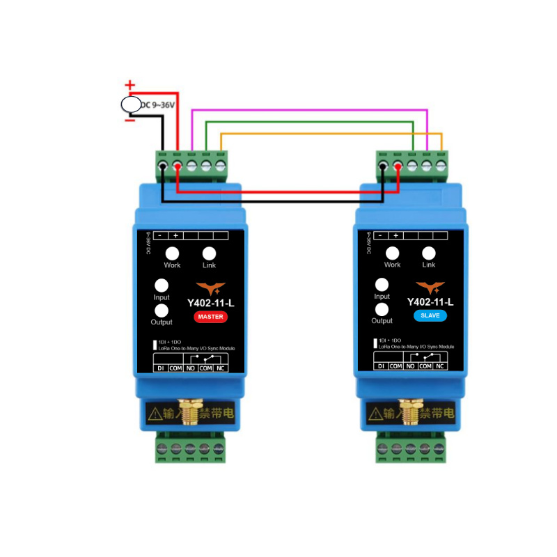
| Y402-11-L / Y402-44-L | Add a new slave by connecting power and the temporary pairing/communication lines to the master or an existing paired slave, then power on and wait for the link indicators to remain on. |
| Y402-4411-L | Power the new slave, press the pairing button on the master and the new slave, then wait for the link indicators to remain on. |
| Y403 | Add a new node by connecting power and the temporary pairing/communication lines to any existing node, then power on and wait for the link indicators to remain on. |
After pairing is complete, remove the temporary pairing/communication lines and test the wireless control logic.
Antenna Installation
| Item | Recommendation |
|---|---|
| Frequency | Use antennas within 398 to 525 MHz |
| Orientation | Install vertically |
| Height | About 2 m above ground or higher when possible |
| Clearance | Keep away from cabinets, walls, pipes, and large metal structures |
| Connector | Tighten the SMA connector by hand |
Good antenna placement improves range more effectively than increasing transmit power. In metal cabinets, lead the antenna outside the cabinet whenever possible.
DI Wiring
DI accepts dry contacts and NPN open-collector outputs. Connect the signal between DI and COM.
No voltage input on DI
Never connect a powered signal or voltage source directly to DI.

For PNP, PLC, or other powered outputs, use an intermediate relay and connect only its dry contact to DI and COM.
DO Wiring Diagrams
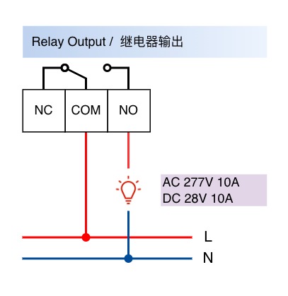
DO is an isolated relay contact output. It can switch small loads directly or drive an external contactor for larger loads.
Small Loads
For lamps, alarm devices, small heaters, and other resistive loads within the relay rating, connect the load power line through COM and NO.
Contactor-Controlled Loads
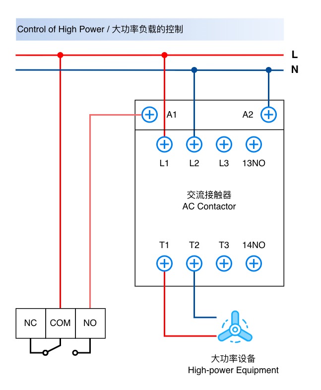
Large Loads
Use the module relay output to drive a properly rated contactor for motors, pumps, heaters, and other high-power loads. The contactor switches the load circuit.
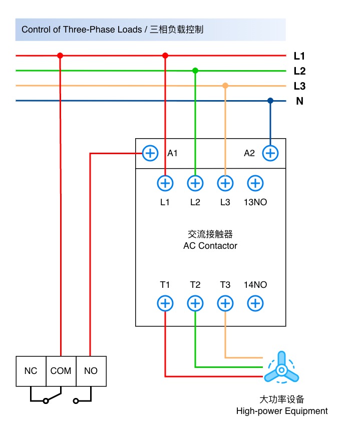
Three-Phase Equipment
Use the module relay output to drive a properly rated contactor for three-phase motors, pumps, and other equipment. The contactor switches the three-phase circuit.
Safety Notes
- Use a certified power supply and confirm polarity before power-up.
- Do not install the device in explosive, high-humidity, corrosive, or heavily dusty environments.
- Do not exceed the relay contact rating.
- Do not use the wireless link as the only protection path for emergency stop, personnel safety, or other hard real-time safety functions.
- High-voltage AC wiring must be performed by qualified personnel.
- Manufacturer: Hunan YenGear Tech Co., Ltd.
- Address: Room 21014, Building 1, Fudi Xingguang Tiandi, Yingxin Road, Yuhua District, Changsha, Hunan, China
- Email: hi@yengear.com
- Website: www.yengear.com