
Appearance
Y901 — Integrated Multi-Point Wireless Alarm System Specification
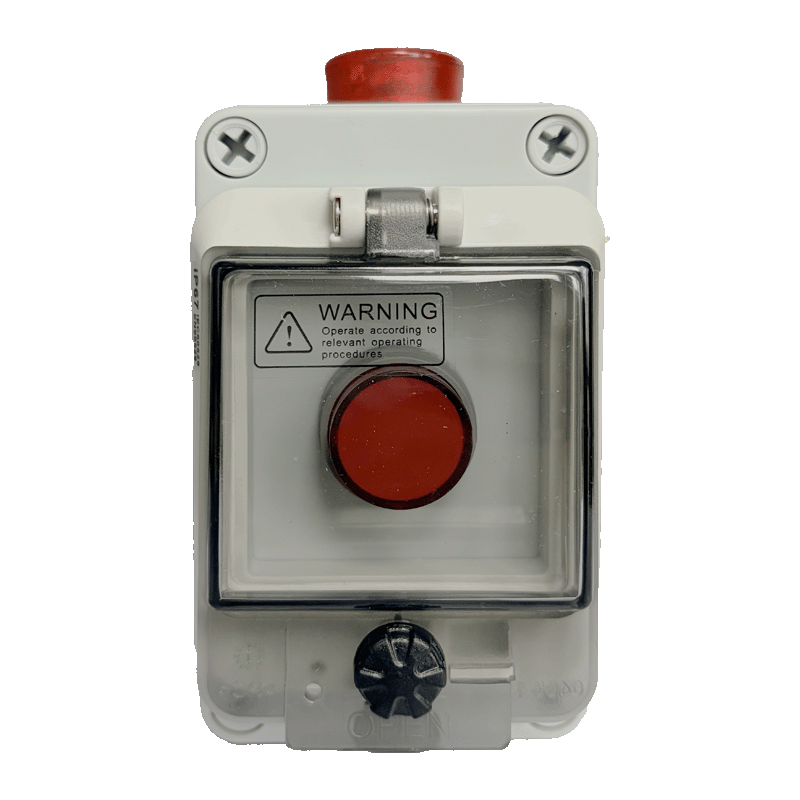
Contents
- Overview
- Ordering Information
- Key Features
- Technical Specifications
- Interfaces and Indicators
- Important Notes
1. Overview
Y901 is an integrated multi-point wireless alarm system. Each node combines a latching push button, wireless linkage control, and an audible-visual alarm in an IP67 enclosure. The product is available in 4G and LoRa versions: Y901-G and Y901-L.
Pressing the latching button on any node starts that node's alarm and synchronizes the trigger state to the other nodes in the same Y901 network. Every node then activates its local audible-visual alarm. The network-wide alarm clears only after every triggered button has been reset.
Trigger Method
The built-in latching button is the only user trigger. Press it once to hold the trigger state; press it again to release and reset it. Y901 does not expose an external DI to the user and does not accept remote alarm-trigger commands from the platform.
Network Architecture
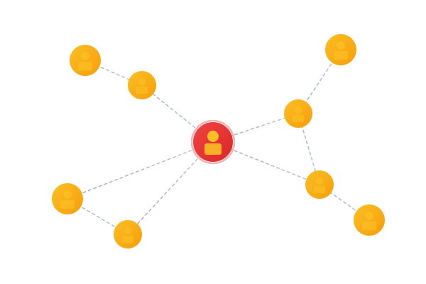
Y901-Luses LoRa multi-node automatic relay networking. The standard open-area range is5 km, with an optional10 kmversion.Y901-Gsynchronizes node trigger states through the existing 4G platform or server. It does not use LoRa automatic relay networking.- Y901 and Y902 form separate networks. Their nodes cannot join the same network.
Operating Principle
- Closing the latching switch on any node puts that node into the alarm state.
- The corresponding 4G or LoRa network synchronizes the trigger state to the other nodes.
- Each receiving node activates its local audible-visual alarm.
- LoRa nodes can relay data and search for a better communication path; 4G nodes exchange status through the platform or server.
- The network-wide alarm stops after all trigger conditions have been cleared.
Typical Applications
- Long tunnels, underpasses, and utility corridors
- Distributed alarm points in production areas, equipment rooms, and pump stations
- Assistance and warning points at construction sites and inspection routes
- Multi-point alarm linkage where control wiring is impractical
- Outdoor, humid, or dusty sites that require a protected enclosure
2. Ordering Information
Model Code
text
Y901-C
  │  └── C: Communication (G / L)
  └───── Y901 series
Communication Suffix
| Suffix | Communication | Application |
|---|---|---|
-G | 4G | Cross-site alarm networks that use the existing platform or server to synchronize trigger states |
-L | LoRa | On-site multi-node linkage with automatic relay networking |
Package Contents
| Quantity | Item |
|---|---|
| 1 | Y901 alarm unit |
| 1 | Antenna |
| 1 | DC power adapter |
3. Key Features
- Integrated alarm node: Combines a latching trigger, wireless linkage control, and an audible-visual alarm.
- Any-node trigger: One triggered node activates every node in the same network.
- LoRa automatic relay:
Y901-Lsupports automatic relay networking, with a standard5 kmopen-area range and an optional10 kmversion. - Built-in trigger: Uses only the built-in latching push button; no user-accessible external DI or remote trigger command is provided.
- Latched alarm state: The trigger remains active until personnel reset the button.
- Wide DC input: Supports
9–36 V DC. - Protected enclosure: The complete unit is rated
IP67. - Two communication options: Available with
4GorLoRa. - Local indication: Provides a
95 dBintermittent audible alarm and flashing red light.
4. Technical Specifications
Communication
| Parameter | Specification |
|---|---|
| Communication | 4G or LoRa |
| Model suffix | -G or -L |
Y901-G architecture | Node-state linkage through the existing 4G platform or server |
Y901-L architecture | LoRa multi-node automatic relay networking |
| LoRa range | Standard 5 km in an open area; optional 10 km version |
| Communication accessories | Supplied for the ordered communication version |
Electrical and Control
| Parameter | Specification |
|---|---|
| Supply voltage | 9–36 V DC |
| Trigger | Built-in latching button; press once to trigger and again to reset |
| Input type | Internal dry-contact input; no external DI exposed to the user |
| Alarm output | Audible-visual alarm |
| Sound level | 95 dB |
| Light pattern | Flashing red light |
| Sound pattern | Intermittent tone |
| Linkage logic | Any triggered node activates all nodes |
| Reset logic | The alarm stops after every trigger source has been reset |
| Typical LoRa control-unit current | 30 mA @ 12 V DC; 15 mA @ 24 V DC, measured average |
| Complete-unit current | Depends on the communication version and alarm state |
The LoRa current values apply to the
Y901-Lcontrol unit and exclude the audible-visual alarm load. Size the power supply and any backup battery for the maximum complete-unit current.
Test the
Y901-G4G control-unit current with the delivered hardware and network state. Do not apply the LoRa current values to the 4G version.
Environment and Construction
| Parameter | Specification |
|---|---|
| Operating temperature | -20 to +85°C |
| Operating humidity | 10–90% RH, non-condensing |
| Product form | Integrated latching trigger, wireless linkage controller, and audible-visual alarm |
| Mounting | Confirmed for the delivered enclosure version |
| Dimensions | Confirmed for the delivered enclosure version |
| Ingress protection | IP67 |
5. Interfaces and Indicators
| Interface or Component | Description |
|---|---|
| Antenna | Antenna supplied for the selected 4G or LoRa version |
| Power input | 9–36 V DC; use a stable DC supply |
| Latching button | The only user trigger; press once to hold and again to reset |
| Audible-visual alarm | Local 95 dB intermittent tone and flashing red light |
6. Important Notes
- Alarm retention: The network-wide alarm remains active while any node stays triggered.
- 4G linkage:
Y901-Gsynchronizes trigger states through the existing platform or server. The platform does not issue user remote-trigger commands to the device. - LoRa linkage:
Y901-Lsupports automatic relay networking, with a standard5 kmopen-area range and an optional10 kmversion. - Network separation: Y901 and Y902 nodes cannot join the same network.
- Input boundary: Y901 uses only its built-in latching button and does not expose an external DI.
- Manual reset: Personnel must reset every triggered button before the system can leave the alarm state.
- Safety boundary: Y901 supports auxiliary alarming and personnel notification. It must not serve as the only emergency-stop, life-safety, or hard real-time safety circuit.
- Antenna installation: Keep the antenna out of enclosed metal spaces and away from strong interference sources.
- Ingress boundary:
IP67does not permit prolonged immersion or abnormal mechanical pressure. - Delivered configuration: Confirm the enclosure, mounting, and structural details from the shipped product documents.
- Manufacturer: Hunan YenGear Tech Co., Ltd.
- Address: Room 21014, Building 1, Fudi Xingguang Tiandi, Yingxin Road, Yuhua District, Changsha, Hunan, China
- Email: hi@yengear.com
- Website: www.yengear.com