
Appearance
Y301-110/200/020 Serial I/O Modules Technical Manual
| Y301-110 | Y301-200 | Y301-020 |
|---|---|---|
 |  |  |
Contents
- Overview
- Default Settings
- Modbus Register Map (Modbus Address Only)
- Command Examples (CRC Included)
- Parameter Configuration
- Automation Rules
- Troubleshooting
1. Overview
Y301-110, Y301-200, and Y301-020 use Modbus RTU for digital input monitoring and relay control.
| Model | DI | DO | Description |
|---|---|---|---|
| Y301-110 | 1 | 1 | Single input + single relay |
| Y301-200 | 2 | 0 | Dual input monitoring |
| Y301-020 | 0 | 2 | Dual relay control |
Frame format: [slave address][function code][data][CRC low][CRC high]
Command examples use slave address 0x01. Replace it with the configured device address and recalculate the CRC.
2. Default Settings
| Parameter | Default |
|---|---|
| Slave address | 1 |
| Baud rate | 9600 bps |
| Data bits | 8 |
| Stop bits | 1 |
| Parity | None |
| Pulse debounce | 50 ms (0x0042 = 50) |
2.1 DI Input Wiring
The Y301-110 and Y301-200 use a DI / DI-COM input pair for each fitted channel. One generic channel is shown for both models; use the terminal names in the table below.
DI input voltage: 5-36 VDC, matching the module power-supply range. This is the excitation voltage used with a passive dry contact, or the active signal voltage applied between DI and its corresponding DI-COM.
| Channel | Signal positive / switched positive | Input return |
|---|---|---|
| Y301-200 DI1 | DI1 | DI1-COM |
| Y301-200 DI2 | DI2 | DI2-COM |
| Y301-110 | DI | DI-COM |
Y301-020 has no DI channels. The drawings show logical connections; they do not specify physical terminal positions.
Confirm the input circuit before wiring
Keep the DI excitation / active signal within 5-36 VDC. Follow the terminal labels on the supplied module; DI-COM is the input return, not the relay's DO common terminal. Power off before changing wiring.
Dry-Contact Input
In the circuit shown, the passive contact switches supply positive into DI. Connect the corresponding DI-COM to supply negative. The same 5-36 VDC source can power the module through its + and - power terminals and provide the DI excitation through the contact.
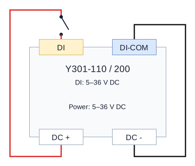
A contact connected only between DI and DI-COM does not complete the excitation circuit shown here. A mechanical rain-gauge reed contact must be used as the switch in the confirmed circuit, rather than treated as a powered signal source.
Wet-Contact Input
Connect each external signal's positive output to its DI terminal and the signal's negative return to the corresponding DI-COM. For Y301-200, repeat the connection separately for DI2 / DI2-COM. The module still needs its own DC power connection.
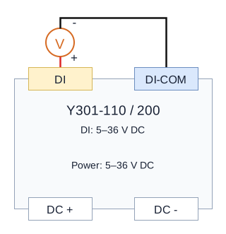
The wet-contact diagram does not add a connection between the signal return and module power negative. Confirm any required grounding or bonding for the supplied hardware and signal source before adding one. The active signal voltage between DI and DI-COM must be within 5-36 VDC.
First Input Check
After confirming the circuit and checking that the excitation voltage is within 5-36 VDC, power off, disconnect the rain gauge from any other logger, and isolate connected DO loads. For the dry-contact test, substitute a known passive switch in the contact position. Power on and hold it closed and open for about one second each. Read the DI state while holding each state, and compare the pulse counter before and after several complete cycles.
- DI1 state: function
0x02, address0x0000, quantity1. - DI1 count: function
0x03, address0x0500, quantity2registers. - Keep the initial debounce setting at
50 msfor this slow test. Register0x0041selects the counting edge;0x0042sets counting debounce. Neither register selects a dry-contact input mode.
A short rain-gauge pulse may be missed by status polling. Check the accumulated counter as well. If the slow switch test works but rain-gauge tips are missed, check the pulse timing and contact bounce before adjusting debounce. If a verified input signal still produces no state change, check terminal contact and compare with another module before concluding that DI is faulty.
3. Modbus Register Map (Modbus Address Only)
3.1 Digital Input (DI) - Function Code 0x02
| Channel | Modbus Address | Supported Models | R/W |
|---|---|---|---|
| DI1 | 0x0000 | Y301-110, Y301-200 | RO |
| DI2 | 0x0001 | Y301-200 | RO |
Return value: 0 = inactive, 1 = active.
3.2 Digital Output (DO) - Function Code 0x01/0x05/0x0F
| Channel | Modbus Address | Supported Models | R/W |
|---|---|---|---|
| DO1 | 0x0000 | Y301-110, Y301-020 | RW |
| DO2 | 0x0001 | Y301-020 | RW |
For function code 0x05, write 0x0000 to open the NO contact or 0xFF00 to close it. Function code 0x0F uses packed bits: 0 = open, 1 = closed.
3.3 Common Holding Registers - Function Code 0x03/0x06/0x10
Holding-register data uses big-endian order. For a 32-bit value, the lower register address contains the high 16-bit word. Each register transmits its high byte first. Read or write both registers together.
| Modbus Address | Parameter | Bytes | R/W | Range / Enum |
|---|---|---|---|---|
0x002A | Runtime slave address | 2 | RO | 0-255 |
0x003E | Slave address | 2 | RW | 1-255 |
0x003F | Broadcast mode | 2 | RW | 0 = disabled; 1 = receive and respond; 2 = receive without response |
0x0041 | Pulse count edge | 2 | RW | 0 = falling; 1 = rising |
0x0042 | Pulse debounce (ms) | 2 | RW | 5-255 |
0x0055 | RTC Unix time | 4 | RW | uint32 |
0x0057 | Baud rate | 4 | RW | 600-230400 |
0x0059 | Data bits | 2 | RW | 8 or 9 |
0x005A | Stop bits | 2 | RW | 1 or 2 |
0x005B | Parity | 2 | RW | 0 = none; 1 = odd; 2 = even |
3.4 DI Pulse Counter Registers
| Channel | Modbus Address | Bytes | R/W | Supported Models | Description |
|---|---|---|---|---|---|
| DI1 count | 0x0500 (0x0500~0x0501) | 4 | RW | Y301-110, Y301-200 | Only 0 is allowed for write (clear) |
| DI2 count | 0x0502 (0x0502~0x0503) | 4 | RW | Y301-200 | Only 0 is allowed for write (clear) |
Each count is a 32-bit unsigned integer (uint32). Use function code 0x03 to read two consecutive registers. For DI1:
text
count = (register[0x0500] << 16) | register[0x0501]For example, data bytes 00 01 00 02 represent 65538. To clear a count, use 0x10 to write zero to both registers.
DI inputs sample at 100 Hz. Register 0x0042 sets the debounce interval in milliseconds. After a counted edge, signals within this interval do not generate another count. Select the interval to reject contact bounce without suppressing valid pulses.
3.5 Automation Rule Register Groups
Rule groups = DO * 2:
| Model | DO Count | Rule Groups | Start Addresses |
|---|---|---|---|
| Y301-110 | 1 | 2 | 0x0080, 0x0088 |
| Y301-200 | 0 | 0 | N/A |
| Y301-020 | 2 | 4 | 0x0080, 0x0088, 0x0090, 0x0098 |
3.6 Reboot and Factory Reset Register
Write to 0x0800 with function code 0x06 to reboot or restore factory settings. This register is write-only.
| Value | Operation |
|---|---|
0x5500 | Reboot |
0x0055 or 0x5555 | Restore factory settings and reboot |
A factory reset restores the device parameters. Record the current settings before using it.
4. Command Examples (CRC Included)
4.1 Read Digital Inputs
| Operation | Request | Supported Models |
|---|---|---|
| Read DI1 | 01 02 00 00 00 01 B9 CA | Y301-110, Y301-200 |
| Read DI2 | 01 02 00 01 00 01 E8 0A | Y301-200 |
| Read DI1~DI2 in one shot | 01 02 00 00 00 02 F9 CB | Y301-200 |
4.2 Read Digital Output Status
| Operation | Request | Supported Models |
|---|---|---|
| Read DO1 | 01 01 00 00 00 01 FD CA | Y301-110, Y301-020 |
| Read DO2 | 01 01 00 01 00 01 AC 0A | Y301-020 |
| Read DO1~DO2 in one shot | 01 01 00 00 00 02 BD CB | Y301-020 |
4.3 Control Digital Outputs
| Operation | Request | Supported Models |
|---|---|---|
| Open DO1 | 01 05 00 00 00 00 CD CA | Y301-110, Y301-020 |
| Close DO1 | 01 05 00 00 FF 00 8C 3A | Y301-110, Y301-020 |
| Open DO2 | 01 05 00 01 00 00 9C 0A | Y301-020 |
| Close DO2 | 01 05 00 01 FF 00 DD FA | Y301-020 |
Multi-channel control (0x0F):
| Operation | Request | Supported Models |
|---|---|---|
| Close DO1 and DO2 together | 01 0F 00 00 00 02 01 03 9E 96 | Y301-020 |
| Open DO1 and DO2 together | 01 0F 00 00 00 02 01 00 DE 97 | Y301-020 |
4.4 Parameter Read/Write
| Operation | Request |
|---|---|
Read slave address (0x003E) | 01 03 00 3E 00 01 E5 C6 |
| Write slave address = 5 | 01 06 00 3E 00 05 28 05 |
Read baud rate (0x0057, 2 regs) | 01 03 00 57 00 02 75 DB |
Write baud rate = 115200 (0x0001C200) | 01 10 00 57 00 02 04 00 01 C2 00 B7 D5 |
Write 8N1 (0x0059~0x005B) | 01 10 00 59 00 03 06 00 08 00 01 00 00 85 EF |
4.5 DI Pulse Counter Read/Write
| Operation | Request | Supported Models |
|---|---|---|
Read DI1 count (0x0500, 2 regs) | 01 03 05 00 00 02 C4 C7 | Y301-110, Y301-200 |
Read DI2 count (0x0502, 2 regs) | 01 03 05 02 00 02 65 07 | Y301-200 |
| Clear DI1 count (write 0) | 01 10 05 00 00 02 04 00 00 00 00 CC FF | Y301-110, Y301-200 |
5. Parameter Configuration
5.1 Serial Settings
- Baud rate is a 32-bit value at
0x0057, use0x10to write 2 registers. - Data/stop/parity are located at
0x0059~0x005B. - Changing serial parameters or slave address requires reboot. Write
0x5500to0x0800with function code0x06, then reconnect using the new settings. - Other configuration parameters take effect immediately after they are written.
5.2 RTC and Scheduled Rules
Write the current Unix time in seconds to 0x0055~0x0056 before using modes 7, 8, or 9. Set the time after each reboot on devices without the optional hardware RTC.
5.3 Pulse Counting Edge
Set 0x0041 to 0 for falling-edge counting or 1 for rising-edge counting.
6. Automation Rules
Y301-110 supports DI -> DO local automation (1DI + 1DO).
Y301-200 has no DO and no output automation rules. Y301-020 supports output rules driven by Modbus commands or time; it has no DI for input-triggered rules.
6.1 Automation Register Map
Rules start at address 0x0080. Each rule uses 8 registers (16 bytes).
| Offset | Field | Description |
|---|---|---|
+0 | Mode | Rule mode number |
+1 | Action | Mode-specific action |
+2 | DO index | Target relay, starting from 1 |
+3 | Trigger index | Source DI, starting from 1; 0 for modes 2-5 and 7-9 |
+4-5 | Parameter 1 | Mode-dependent, 32-bit |
+6-7 | Parameter 2 | Mode-dependent, 32-bit |
6.2 Rule Modes
| Mode | Name | Action / Parameters | Applicable Models |
|---|---|---|---|
| 0 | Disabled | Disable this rule | Y301-110, Y301-020 |
| 1 | DI follow | 0 = inverse, 1 = forward; select the source DI | Y301-110 |
| 2 | Pulse output | 0 = normally open, 1 = normally closed; parameter 1 = pulse duration (ms) | Y301-110, Y301-020 |
| 3 | Delayed control | 0 = delay opening commands, 1 = delay closing commands, 2 = delay both; parameter 1 = delay (ms) | Y301-110, Y301-020 |
| 4 | Timed change after reboot | 0 = open, 1 = close, 2 = toggle; parameter 1 = delay after reboot (ms) | Y301-110, Y301-020 |
| 5 | Cyclic change | 0 = open first, 1 = close first; parameter 1 = open duration, parameter 2 = closed duration (ms) | Y301-110, Y301-020 |
| 6 | Button input | 0 = open, 1 = close, 2 = toggle; select DI; parameter 1 = minimum active duration (ms) | Y301-110 |
| 7 | Scheduled once | 0 = open, 1 = close, 2 = toggle; parameter 1 = Unix timestamp (s) | Y301-110, Y301-020 |
| 8 | Scheduled repeating | 0 = open, 1 = close, 2 = toggle; parameter 1 = Unix timestamp (s), parameter 2 = repeat interval (ms) | Y301-110, Y301-020 |
| 9 | Daily schedule | 0 = open, 1 = close, 2 = toggle; parameter 1 = seconds since the start of the day (0-86399) | Y301-110, Y301-020 |
| 14 | Delayed DI follow | 0 = inverse, 1 = forward; select DI; parameter 1 = follow delay (ms) | Y301-110 |
| 15 / 16 / 17 | Logic AND / OR / XOR | Parameter 1 = DO mask, parameter 2 = DI mask; trigger an action or hold an output state | Y301-110 (DI/DO conditions), Y301-020 (DO conditions) |
Modes 10-13 require AI inputs. Y301-110, Y301-200, and Y301-020 have no AI inputs.
For logic modes, bit 0 selects channel 1 and bit 1 selects channel 2. Use channels present on the model. Select the logic action in the configuration tool: open, close, or toggle on a trigger, or hold the output open or closed while the condition is true.
The minimum delay or interval is 10 ms in modes 3, 4, 5, 8, and 14. In button mode, the action triggers when the DI returns inactive after meeting the minimum active duration. When rules conflict, the later rule takes precedence.
Mode 2 responds to a Modbus output-control command: configuring the rule alone does not issue the pulse. Mode 3 delays an output-control command; it is distinct from mode 14, which follows a DI change after a delay.
6.3 Rule Command Examples (Y301-110)
- Case 1: DI Follow (Mode 1): DO1 follows DI1
| Field | Value | Description |
|---|---|---|
| Mode | 0x0001 | DI follow |
| Action | 0x0001 | Forward follow |
| DO index | 0x0001 | DO1 |
| DI index | 0x0001 | DI1 |
| Parameter 1 | 0x00000000 | Not used |
| Parameter 2 | 0x00000000 | Not used |
text
01 10 00 80 00 08 10 00 01 00 01 00 01 00 01 00 00 00 00 00 00 00 00 CC FE- Case 2: Pulse Output (Mode 2): DO1 normally open, auto-recover after 500 ms close
| Field | Value | Description |
|---|---|---|
| Mode | 0x0002 | Pulse output |
| Action | 0x0000 | Normally open |
| DO index | 0x0001 | DO1 |
| DI index | 0x0000 | Not used |
| Parameter 1 | 0x000001F4 | 500 ms |
| Parameter 2 | 0x00000000 | Not used |
text
01 10 00 80 00 08 10 00 02 00 00 00 01 00 00 00 00 01 F4 00 00 00 00 30 EA7. Troubleshooting
| Symptom | Cause | Solution |
|---|---|---|
| No response | Wrong address, serial settings, or wiring | Check the configured slave address, baud rate, data bits, parity, stop bits, and RS485 wiring. Broadcast mode is disabled by default; address 0 is not a reliable response test. |
| CRC error | Wiring issue or interference | Check RS485 polarity and add termination resistors |
| DO does not switch | Load exceeds rating | Reduce the load and verify contact ratings |
| DI always reads 0 | Missing excitation, incorrect wiring, or input signal outside the permitted limits | Follow the confirmed DI circuit in Section 2.1; check input polarity, return connection, excitation voltage, and terminal contact. |
LED Indicators
| LED | Status | Meaning |
|---|---|---|
| POWER | Solid on | Power is normal |
| TX | Flashing | Data is being transmitted |
| RX | Flashing | Data is being received |
- Manufacturer: Hunan YenGear Tech Co., Ltd.
- Email: hi@yengear.com
- Website: www.yengear.com