
Appearance
Y953 Wireless Control Cabinet Specification
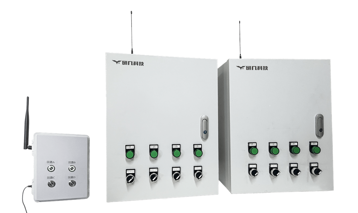
This specification covers the Y953 system components, models, functions and parameter limits. Node count, radio range, load circuits and enclosure design depend on the selected configuration and site conditions.
Contents
- Overview
- Ordering Information
- Functions and Options
- Network Layout and Configuration
- Technical Specifications
- Control Architecture and Operation
- Communication, Range and Lost-Link Behavior
- Mechanical, Installation and Commissioning
- Important Notes
1. Overview
Y953 is the wireless control cabinet in the YenGear smart distribution box range. A controller talks to one or more wireless control cabinets over a site LoRa link. It suits sites with no external network, or where control cables are hard or costly to run.
AC input is confirmed by project, nameplate and order. 220 V and 380 V are project references, not general ratings. The delivered configuration sets 50 Hz or 60 Hz; dual-frequency use requires an explicit rating. The installed components and their test documents set protection thresholds, trip times, breaking capacity and measurement accuracy. Check certification against the delivered configuration and destination market.
Basic control does not depend on 4G, Wi-Fi, Ethernet or a cloud platform. Phone, cloud or cross-site management needs a separate uplink gateway.
Radio and power notice: The frequency band, transmit power, antenna, channel plan and installation must comply with the radio rules of the destination market. Controller, cabinet and repeater power supplies must match their nameplates.
How It Works
- The Y953T controller selects a circuit and sends a LoRa command.
- The LoRa link carries the command to one or more Y953 cabinets. Y953B repeaters forward the signal over long distances or around obstacles.
- The cabinet receives the command, switches the field circuit and, as configured, reports the circuit-closed state back to the controller.
- One controller can manage several dispersed nodes. Node count, distance, topology and repeater positions follow the site layout.
- Local manual control stays available at the cabinet. The project documents set the priority among wireless commands, automatic logic, manual operation and safety interlocks.
Typical Applications
- Sites without
4G,Wi-Fior wired network that still need to switch several circuits or actuators - Equipment far from the control point, where control cables are hard or expensive to install
- Greenhouse zones with fans, roll-up vents, irrigation and grow lights
- Aquaculture ponds with aerators, pumps and valves
- Pump stations and farmland with dispersed equipment under one controller
- Sites where hills or buildings block the path and repeaters are needed
2. Ordering Information
Model Naming
text
Y953T-xx-L  Controller
Y953-xx-L   Wireless control cabinet
Y953B-xx-L  Repeater
     │ │ └── L: LoRa
     │ └──── xx: circuit count (1 or 4)
     └────── T: controller; B: repeater; no letter: wireless control cabinet
Model Matrix
| Device | 1 Circuit | 4 Circuits | Main Function |
|---|---|---|---|
| Controller | Y953T-1-L | Y953T-4-L | Sends LoRa commands and shows the closed state of associated circuits |
| Wireless control cabinet | Y953-1-L | Y953-4-L | Receives LoRa commands and switches the field circuits |
| Repeater | Y953B-1-L | Y953B-4-L | Forwards the LoRa signal; quantity and position follow distance and obstacles |
In the model code, 1 means one circuit, 4 means four circuits and L means LoRa. Control logic, power supply, feedback and enclosure details follow the documents for each model.
Every wireless control cabinet has a built-in Y406 LoRa wireless controller module, so an optional Y406T handheld remote can operate it on site. Y953-1-L uses Y406-22-L, with one of its two circuits kept as a redundant circuit. Y953-4-L uses Y406-44-L.
Standard, Optional and Project Scope
| Scope | Content |
|---|---|
| Standard architecture | Y953T controller, site LoRa link, one or more Y953 cabinets, circuit on/off control and controller status display |
| Options | Y406T handheld remote, one or more Y953B repeaters, solar power system, uplink gateway, cloud platform or other management access |
| Project definition | Node count, topology, distance, obstacles, loads, feedback, lost-link strategy, interlocks and enclosure design |
Order Checklist
| Item | Details to Provide |
|---|---|
| Controller | Mounting location, operators, power supply, circuit count and operating interface |
| Wireless cabinets | Quantity, locations, power supply, circuit count, loads and mounting |
| Repeaters | Whether needed, quantity, locations, power supply, antenna and maintenance access |
| Handheld remote | Whether needed, quantity, key layout and labels, and which cabinets each remote pairs with |
| Radio environment | Straight-line distance, hills, buildings, trees or metal structures in the path, interference and mounting height |
| Controlled equipment | Pumps, fans, valves, lighting, motors, roll-up vents or other equipment |
| Load conditions | Voltage, power, rated current, starting current, starting method and reversing |
| Status feedback | Circuit-closed state, contactor state, load running feedback, fault or lost-link state |
| Lost-link strategy | Hold, stop, safe state, manual reset and local manual operation |
| Power supply | Mains availability, controller and node consumption, and whether solar power is needed |
| Uplink management | Whether 4G, Wi-Fi, Ethernet, phone access, a cloud platform or history records are needed |
| Enclosure and environment | Indoor or outdoor, temperature, ingress protection, material, dimensions, handling and service space |
3. Functions and Options
| Function or Parameter | Specification and Configuration |
|---|---|
| Wireless link | Site LoRa link; basic control works without Internet |
| Control architecture | One controller runs one or more wireless cabinets |
| Local operation | Manual control stays available; priority and interlocks with wireless control are set by configuration |
| Remote operation | Built-in Y406 LoRa module; optional Y406T handheld remote for one-to-one or one-to-many control |
| Standard load | 2.2 kW per circuit, customizable |
| Optional equipment | Y406T handheld remote, Y953B repeaters, solar power system and uplink gateway |
4. Network Layout and Configuration
Network Layouts
| Layout | Components | When to Use |
|---|---|---|
| Direct | Controller → one or more cabinets | Clear path and distance within direct coverage |
| Single repeater | Controller → one Y953B → cabinets | One obstacle to cross, or extra distance needed |
| Multiple repeaters | Controller → one or more Y953B → cabinets | Several obstacles or very long distance; plan the repeater route |
| Solar power | Solar power system → specified devices | Device location lacks stable mains power; the project sets the supplied devices and capacity |
Configuration Steps
- Define the control goal: control without an external network, or control over a long or hard-to-wire distance.
- Mark control points and nodes: record where the controller, each cabinet and the main loads sit.
- Check distance and obstacles: measure the distance to the farthest node and note hills, buildings, trees, greenhouse frames and metal structures.
- Choose the layout: use a direct link for a clear path within direct coverage; plan one or more repeaters for obstacles or long distance.
- Match circuits and loads: pick the 1-circuit or 4-circuit model and check the power, starting method and protection of each pump, fan, valve or motor.
- Set the feedback scope: decide whether circuit-closed state is enough, or whether contactor, auxiliary contact, current or running feedback is needed.
- Review power and uplink: check mains and service access; consider solar power where mains is impractical and an uplink gateway for cross-site management.
- Finalize with a site test: the wireless module documents, network plan, wiring diagram, control logic and site test results define the final system.
5. Technical Specifications
Y953 Series Parameters
| Parameter | Y953 Series |
|---|---|
| Product type | Wireless control cabinet system |
| Control architecture | Point-to-multipoint site wireless control |
| Wireless technology | LoRa |
| Controller | Y953T-1-L / Y953T-4-L |
| Field unit | Y953 wireless control cabinet |
| Repeater | Y953B-1-L / Y953B-4-L, optional by project |
| Direct link range | Up to 10 km without obstruction; actual range depends on site conditions |
| Repeater use | One or more repeaters; quantity, positions, route and total coverage follow the network plan |
| Controller circuits | 1-circuit or 4-circuit models |
| Cabinet circuits | 1-circuit or 4-circuit models |
| Node count | One or more cabinets, set by the network layout and site conditions |
| Built-in wireless module | Y406 LoRa wireless controller module; Y953-1-L uses Y406-22-L with one redundant circuit; Y953-4-L uses Y406-44-L |
| Handheld remote | Optional Y406T remote; one-to-one or one-to-many control |
| Remote range | Up to 3 km without obstruction; actual range depends on site conditions |
| Load capacity | 2.2 kW per circuit as standard, customizable; check load type, rated current and starting conditions |
| Control feedback | Controller shows the closed state of associated circuits; other feedback by configuration |
| Lost-link behavior | Cabinet holds the circuit state from before the link loss; manual operation and safety strategy set by project |
| Uplink management | Gateway, cloud platform or other management access can be added by project |
| Solar power | Optional by project; supplied devices and capacity are sized for the site |
| Enclosure material, dimensions and protection | Set by the site environment, node type and enclosure design |
Radio Parameters to Define
| Area | Minimum Details |
|---|---|
| Module and band | Wireless module model, frequency band, transmit power, receive conditions and antenna type |
| Topology | Direct, single-repeater or multi-repeater layout, node addresses, groups and repeater route |
| Range | Straight-line distance from the control point to each node, obstacles, mounting height and site test results |
| Performance | Command response, feedback interval, retries, packet-loss handling and simultaneous control |
| Power | Input voltage, consumption and backup needs of the controller, cabinets and repeaters |
| Safety | Address management, permissions, interlocks, hold-on-link-loss, manual reset and local manual path |
| Solar extension | PV power, battery capacity, autonomy in cloudy weather and low-battery strategy |
Load and Control Parameters
| Area | Requirement |
|---|---|
| Circuit type | On/off, pulse, latching, reversing or other logic |
| Load type | Pumps, fans, valves, motors, lighting, roll-up vents and similar |
| Starting method | Direct-on-line, contactor, soft starter, VFD or custom |
| Feedback type | Circuit closed, contactor state, auxiliary contact, current feedback or other running feedback |
| Protection | Overload, short circuit, phase loss, overvoltage, undervoltage and other protection by configuration |
6. Control Architecture and Operation
Components
| Component | Role |
|---|---|
| Y953T controller | Selects the target node and circuit, sends LoRa commands and shows associated circuit state |
| LoRa link | Carries commands and status between the controller, repeaters and cabinets |
| Y953B repeater (optional) | Forwards the LoRa signal to extend coverage or route around obstacles |
| Y953 wireless control cabinet | Receives commands, switches field circuits and reports the configured closed state |
| Y406T handheld remote (optional) | Sends commands directly to the built-in Y406 module of paired cabinets |
| Field loads | Pumps, fans, valves, motors, lighting, roll-up vents and other controlled equipment |
| Solar power system (optional) | Powers specified devices on site; supplied devices and capacity are set by project |
| Uplink gateway (optional) | Links the site wireless network to a cloud platform or other management system |
Normal Control Sequence
- The controller selects the target cabinet and circuit.
- The controller sends an on, off or other approved command over LoRa.
- The cabinet receives and validates the command, then switches the circuit.
- The cabinet reports the circuit-closed state or other configured feedback.
- The controller updates the state; with an uplink gateway, the state can also sync to the management system.
Controller Indicator Meaning
A lit circuit lamp on the controller means the matching circuit of an associated cabinet is closed. When one controller runs several cabinets, the lamp lights if any associated cabinet has that circuit closed. The lamp does not show that the load is running, and it does not identify which cabinet closed the circuit.
When a Y406T remote is used, its RX acknowledgement only shows that the module received the command. Check at the equipment whether the load started.
Manual and Automatic Control
Keep wireless control and local manual control as separate operating paths. Record the priority among wireless control, local manual operation, automatic logic and safety interlocks in the wiring diagram and control logic. For pumps, motors and roll-up vents, also define stop, reset and restart conditions.
7. Communication, Range and Lost-Link Behavior
Direct and Repeater Links
- In a direct layout, the controller links straight to one or more cabinets.
- The direct link reaches up to
10 kmwithout obstruction. Actual range depends on site conditions, and coverage through repeaters needs a site test. - Where hills or buildings block the path, or the distance exceeds direct coverage, add one or more Y953B repeaters at suitable positions.
- Base the repeater model, quantity, positions, mounting height, route and total coverage on the site plan and a communication test.
Normal Communication
With a working link, the controller sends commands to multiple cabinets and receives the configured circuit state. The wireless module and control logic define response time, feedback interval, retries and state meanings.
Link Loss
- The cabinet stops receiving new LoRa commands, and the controller should show or record the lost-link state.
- The cabinet holds the circuit state from before the link loss. It does not switch off on its own.
- During link loss, site staff can still switch circuits on or off at the cabinet; manual priority follows the configuration.
- If a load must stop, enter a safe state or wait for manual reset after link loss, design, approve and test that logic for the project.
- For pumps, motors, roll-up vents and other loads with mechanical or personal risk, do not treat the controller display or link recovery as a site safety check.
Relation to Cloud Platforms
Site LoRa control is not the same as cloud remote control. Without an uplink gateway, basic site wireless control runs on its own. With a gateway, define permissions, latency, link loss, reset and fault handling separately for the cloud platform, Internet connection, gateway and site LoRa link.
8. Mechanical, Installation and Commissioning
Site Survey
- Mark the positions of the controller, every cabinet, repeaters and main loads.
- Measure the straight-line distance from the controller to each node and record hills, buildings, trees, greenhouse frames, metal equipment and other obstacles.
- Check mounting height, antenna position, power supply and service access for the controller, nodes and repeaters.
- Check for radio interference, then choose a direct link, the repeater count and the repeater route.
- Where mains power is impractical, define the relationship between solar panels, batteries, the power control unit and the specified loads.
Installation and Wiring
- Install the controller, cabinets, repeaters and loads to the project wiring diagram, with clear node address and circuit labels.
- Keep antennas away from high-current wiring, enclosed metal spaces and strong interference sources; follow the module documents for mounting.
- Qualified personnel must complete power wiring, contactors, protection devices and motor reversing interlocks.
- Define local manual operation, wireless control, automatic logic and safety interlocks separately. Do not rely on the controller display alone.
Commissioning and Acceptance
Complete at least the following tests and keep the records:
- Check the model, node address, circuit number and controlled equipment of each node.
- With a working link, test on, off and status reporting for every node.
- Test one-to-many control, simultaneous control of several nodes, repeated commands, restart recovery and fault indication.
- Verify the actual coverage of the direct or repeater link and record the test positions, route and results.
- Force a link loss and verify the lost-link indication, held circuit state, local manual operation and staff response procedure.
- With a Y406T remote, test each paired cabinet and circuit at the intended operating positions.
- With an uplink gateway, test site wireless control, gateway uplink, cloud management and network recovery separately.
- With solar power, test power switching, low-battery indication, autonomy strategy and recovery conditions.
- Complete real-load operation and interlock tests on pumps, motors, valves and roll-up vents before handover.
9. Important Notes
- Product role: Y953 handles wireless control from one control point to several dispersed nodes. It is not the same as Y951 Internet remote control.
- Network scope: Basic LoRa control does not depend on
4G,Wi-Fi, Ethernet or a cloud platform. Cross-site management needs a separate uplink. - Range: The direct link reaches up to
10 kmwithout obstruction, and the handheld remote up to3 km. Site testing sets the usable range. - Repeaters: Repeater quantity, positions, route and total coverage come from the site plan and a communication test.
- Link loss: Circuits hold their state on link loss. Stop-on-loss, safe-state actions or manual reset need separate design and testing.
- Status indication: A lit controller lamp means an associated circuit is closed. It does not show that a pump, motor or other load is running, or which node closed the circuit. A remote RX acknowledgement only means the module received the command.
- Load rating: The standard rating is 2.2 kW per circuit, and higher ratings can be built to order. Motors, pumps, valves and roll-up vents also need checks of starting current, direction, interlocks and protection.
- Power: The solar power system is a project option. PV power, battery capacity, autonomy and low-battery strategy are sized for the site.
- Qualified work: Personnel with relevant experience or qualifications must carry out power installation, protection setup, radio survey and commissioning.
- Document priority: Wireless module documents, the node list, wiring diagrams, control logic, site test records and the product confirmation take precedence over this series overview.
Related Products
Y951 handles connected remote control, Y952 handles local temporary-power protection and event records, and Y953 handles site wireless control. A control display is not load running feedback. Alarms, monitoring, local rules and external platform functions depend on the project configuration.