
Appearance
Y201-L Technical Manual

Contents
- Overview
- Default Settings
- Serial Modes and Packetization
- LoRa Parameters and Communication Modes
- AT Command Conventions
- Common AT Commands
- Typical Configuration Flow
- Maintenance and Upgrade
- Troubleshooting
1. Overview
This manual explains configuration, commissioning, maintenance, and troubleshooting for the Y201-L mini LoRa DTU. It covers the serial AT command set, transparent and command modes, LoRa communication modes, relay networking, firmware upgrade, and parameter recovery.
| Item | Description |
|---|---|
| Frequency Band | 410 to 493 MHz |
| Serial Interface | Single-port RS232, RS485, or 3.3 V TTL, depending on the ordered variant |
| Communication Distance | Up to 5 km |
| Working Modes | Broadcast, fixed-point, master-slave, relay networking |
| Configuration Method | Serial AT commands |
1.1 Hardware Wiring
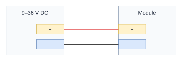
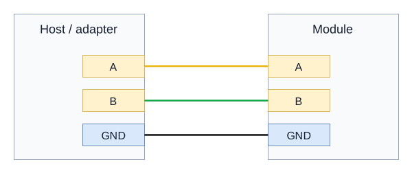
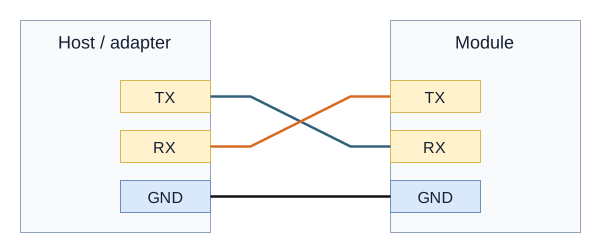
Power off before wiring. Select the ordered serial interface and use the terminal labels on the supplied module. The drawings show electrical connections, not connector pin order.
Module power: 9-36 VDC. Connect supply positive to + and negative to -.
RS485 variant: A to A, B to B, signal GND to GND. TX/A and RX/B are the shared terminal labels. Use a twisted pair and terminate only the two physical bus ends when required.
RS232 / TTL variant: cross TX and RX; connect GND to GND. Match the adapter's electrical interface and verify the TTL logic voltage before connecting.
See the Y201 User Manual for model-specific power and uplink connections.
1.2 Working Principle
Two RS485 Y201-L units provide a bidirectional LoRa link between a Modbus RTU master and a field device.

The PLC or data logger sends a Modbus request through the host-side Y201-L. The field-side Y201-L delivers it to the RS485 device, then carries the response back to the host. The DTUs forward serial data; the host controls polling and uses the field device's slave address and register map.
For pulse-counting I/O, the counter remains in the I/O module. The host reads that counter over the wireless link. Use transparent serial mode and LoRa broadcast mode (BRD) for this example; FP and MS modes require the additional framing described in Section 4.
2. Default Settings
| Parameter | Default |
|---|---|
| Serial Baud Rate | 9600 bps |
| Data Bits | 8 |
| Stop Bits | 1 |
| Parity | NONE |
| Serial Mode | Transparent mode |
| Hardware Flow Control | NFC |
| Base Frequency | 410 MHz |
| Step | 1 MHz |
| Channel | 20 |
| Speed Level | 5 |
| LoRa Mode | Broadcast mode, BRD |
| Retransmission Count | 0 |
| Retransmission Interval | 1000 ms |
| Relay | OFF |
| Relay Group ID | 0 |
| Relay Rule | 0,0 |
3. Serial Modes and Packetization
3.1 Serial Modes
Y201-L supports two serial working modes:
- Transparent Mode, default: Serial data is packetized and forwarded through LoRa
- AT Command Mode: Serial input is treated as AT commands and downlink data is not transparently forwarded
3.2 Entering AT Command Mode
Recommended sequence:
- Send
+++. - Wait longer than the packet interval and less than
3 s;500 msis recommended. - Send
a. - Enter AT mode only after receiving
+ok.
Notes:
- The device pauses data output for about
3 safter receiving+++ - Send AT queries and settings only after
+okis returned - AT mode is not saved across power cycles; the device returns to transparent mode after reboot
3.3 Exiting AT Mode
- Send
AT+EXIT\r\nand wait forOK. - Or reboot the device directly
3.4 Packetization
Serial data is transmitted when either condition is met:
- Length trigger: data length
>=packet length, default252, range5 to 252 - Interval trigger: inter-character gap
>=packet interval, default5 ms, range0 to 300 ms
4. LoRa Parameters and Communication Modes
4.1 Key Parameters
| Parameter | Meaning | Default |
|---|---|---|
Base Frequency, base | Frequency calculation baseline | 410 MHz |
Step, step | Frequency interval between adjacent channels | 1 MHz |
Channel, ch | Working channel number | 20 |
Speed, sp | LoRa speed level, 1 to 9; higher speed shortens the relative transmission distance | 5 |
Key, key | LoRa encryption string, 1 to 16 characters; write-only | No default |
Device Address, id | Local address in fixed-point or master-slave mode, 0 to 65535 | No default |
Frequency formula: F = base + step x ch.
The configuration tool displays the base frequency and step in 100 kHz units. For example, 4100 represents 410.0 MHz, and 10 represents a 1 MHz step.
4.2 Broadcast Mode, BRD
- Data is broadcast only and not modified
- Both ends must use the same base frequency, step, channel, and speed
- No extra protocol framing is required
4.3 Fixed-Point Mode, FP
Transmit frame format in hex:
[Target Address(2B)][Target Channel(1B)][Data(nB)][XOR(1B)]
Examples:
- Send to address
0x0001, channel0x03, data01 02 03:00 01 03 01 02 03 02 - Use target address
0xFFFFin fixed-point mode for broadcast transmission
4.4 Master-Slave Mode, MS
- The master must frame data according to the master-slave protocol
- The slave returns uplink data transparently
- Configure the retransmission interval and count to reduce packet loss
Master transmit frame format:
[Target Address(2B)][Data(nB)]
4.5 Relay Networking
Relay networking works with broadcast, fixed-point, and master-slave modes.
Key parameters:
AT+RELAY: relay enableAT+GROUPID: relay group IDAT+RELAYRULE: relay input and output rules
Typical rules:
- The sender group ID must match the input rule of the first relay
- The input rule of each relay must match the output rule of the previous relay
- The receiver group ID must match the output rule of the last relay
Contact YenGear to confirm the relay-rule settings for your deployment.
5. AT Command Conventions
5.1 Command Format
- Commands start with
AT+and end with\ror\n - Commands are case-insensitive, uppercase is recommended
- Maximum command length is
256 bytes,252 bytesrecommended - Multiple parameters are separated by commas
- Wait for the previous response before sending the next command, maximum timeout about
12 s
5.2 Call Types
| Type | Send Format | Return Format |
|---|---|---|
| Query | AT+CMD or AT+CMD? | +CMD:value followed by OK |
| Set | AT+CMD=value1,value2... | OK |
| Help | AT+CMD=? | +CMD:(range...) followed by OK |
5.3 Common Error Codes
| Error Code | Meaning |
|---|---|
ARGS | Invalid parameter, length, format, or range |
ARGC | Invalid number of parameters |
CMD_UNKNOWN | Unknown command |
CMD_FORMAT | Invalid command format |
CMD_LENGTH | Command too long |
UN_VIEW | Write-only parameter |
DEV_MEMORY | Memory error |
DEV_SAVE | Parameter save failed |
6. Common AT Commands
6.1 Device and System
| Command | Function | Notes |
|---|---|---|
AT+LIST | List supported commands | Use to list commands |
AT+VER | Query firmware version | Returns version string |
AT+DEVINFO | Query device information | Model, version, SN, and more |
AT+ECHO | Enable or disable command echo | ON / OFF; default OFF |
AT+BOOTINFO | Set or query boot information | 1 to 16 bytes; default Start |
AT+REBOOT | Reboot device | Parameters take effect in the current runtime area |
AT+EXIT | Exit AT mode | Returns to transparent mode |
AT+RSTCFG | Restore backup parameters and reboot | Equivalent to Reload |
AT+BKCFG | Back up current parameters | Recommended after commissioning |
AT+CLRCFG | Restore factory parameters and reboot | Full factory reset |
6.2 Serial Parameters
| Command | Parameter | Range / Default |
|---|---|---|
AT+UART1=<baud>,<data>,<stop>,<parity> | Serial settings | baud 1200 to 460800, default 9600; data 7/8, default 8; stop 1/2, default 1; parity NONE/EVEN/ODD, default NONE |
AT+UARTTL1=<tm>,<len> | Packet interval and length | tm 0 to 300 ms, default 5; len 5 to 252, default 252 |
6.3 Basic LoRa Parameters
| Command | Parameter | Range / Default |
|---|---|---|
AT+SPEED=<sp> | LoRa speed level | 1 to 9, default 5 |
AT+KEY=<key> | LoRa encryption string | 1 to 16 characters, write-only |
AT+FREQ=<base>,<step> | Base frequency and step | Example 4100,10, see note below |
AT+CH=<ch> | Channel number | Determines frequency with base and step |
AT+WMODE=<mode> | LoRa mode | BRD / FP / MS |
AT+ADDR=<id> | Local device address | 0 to 65535 |
Note: The configuration tool displays the base frequency and step in 100 kHz units. Use 4100,10 for a 410.0 MHz base and a 1 MHz step.
6.4 Master-Slave and Relay Parameters
| Command | Parameter | Default |
|---|---|---|
AT+TMODE=<mode> | MASTER or SLAVE | Depends on device role |
AT+RETRANS=<time>,<count> | Retransmission interval in ms and retransmission count | 1000,0 |
AT+RELAY=<state> | ON / OFF | OFF |
AT+GROUPID=<id> | Relay group ID, 0 to 255 | 0 |
AT+RELAYRULE=<rule1>,<rule2> | Relay input and output rules, 0 to 255 | 0,0 |
Contact YenGear to confirm the relay-rule settings for your deployment.
7. Typical Configuration Flow
7.1 Quick Broadcast Configuration
- Enter AT mode,
+++ -> delay -> a -> +ok. - Configure both devices with matching wireless parameters:
text
AT+FREQ=4100,10
AT+CH=20
AT+SPEED=5
AT+WMODE=BRD- Set serial parameters if required:
text
AT+UART1=9600,8,1,NONE
AT+UARTTL1=5,252- Back up the current configuration for later recovery:
text
AT+BKCFGParameter changes are saved to the runtime parameter area automatically. AT+BKCFG creates a separate backup used by AT+RSTCFG and Reload.
- Reboot and verify the link:
text
AT+REBOOT7.2 Fixed-Point Mode Configuration
- Set both ends to the same base frequency, step, and speed:
text
AT+FREQ=4100,10
AT+SPEED=5- Set device addresses:
text
AT+ADDR=1
AT+ADDR=2- Switch to fixed-point mode:
text
AT+WMODE=FP- Send data using the fixed-point frame format.
7.3 Master-Slave Mode Configuration
- Match the base frequency, step, channel, and speed on both devices.
- On the master, set
AT+WMODE=MSandAT+TMODE=MASTER. - On the slave, set
AT+WMODE=MSandAT+TMODE=SLAVE. - Set retransmission strategy if needed:
text
AT+RETRANS=1000,0- The master sends framed master-slave messages and the slave returns data transparently.
7.4 Relay Networking Suggestions
- Complete the base communication mode configuration first, broadcast, fixed-point, or master-slave.
- Enable relay on each node with
AT+RELAY=ON. - Build the group ID and relay rule chain:
- Sender group ID = first relay input rule
- First relay output rule = second relay input rule
- Receiver group ID = last relay output rule
- After validating the multi-hop link, run
AT+BKCFGto save.
7.5 Modbus RTU Communication Check
- Read a known register from the field device over a direct wired connection first. Record the serial settings, slave address, function code, starting address, and register count.
- With power off, fit the LoRa antennas and connect one RS485 Y201-L to the field device and the other to the host. Follow the power and RS485 wiring in Section 1.1.
- Configure the pair using Section 7.1. Match each DTU's serial settings to its connected device, and match the LoRa base frequency, step, channel, speed, and encryption key if configured. Reboot both DTUs to apply the settings and return to transparent serial mode.
- Send the same Modbus request from the host. Allow for radio transfer and packetization delays in the response timeout. Start with one request at a time and wait for its response or timeout before sending another.
- Check the TX/RX indicators and compare the returned register data with the field device's expected value. For a pulse counter, generate a known number of pulses and verify the corresponding count change.
8. Maintenance and Upgrade
8.1 Parameter Partitions
The device uses three parameter areas:
- Runtime Area: Current running configuration, query and set commands act on this area
- Backup Area: Saved by
AT+BKCFG - Factory Area: Factory-fixed default parameters
New parameter values are saved to the runtime area automatically and take effect after reboot. AT+BKCFG copies the current runtime values to the backup area.
Recommended workflow:
- Finish parameter commissioning.
- Run
AT+BKCFGto create a backup. - Use
AT+RSTCFGwhen rollback is needed. - Use
AT+CLRCFGfor a full factory reset.
8.2 Firmware Upgrade
Upgrade steps:
- Power off the device.
- Hold the Reload button while powering on and release it after about
3 sto enter upgrade mode. - Select the firmware file in the configuration tool and start the upgrade.
Firmware upgrade usually keeps saved parameters. Back up parameters first as a precaution.
9. Troubleshooting
| Symptom | Possible Cause | Recommended Action |
|---|---|---|
| Cannot enter AT mode | The timing is incorrect or +ok was not received | Retry with +++ -> 500 ms delay -> a |
Command returns CMD_FORMAT | The command does not start with AT+ or has no line ending | Check command format and serial line ending |
Command returns ARGS/ARGC | Wrong parameter value or parameter count | Run AT+CMD=? to view the valid range |
| LoRa link does not work | Frequency, step, channel, or speed does not match | Check FREQ / CH / SPEED on both ends |
| Modbus works over a cable but times out over LoRa | The host timeout is too short, a DTU is still in AT mode, or serial/radio settings differ | Follow Section 7.5; check transparent mode and settings, then allow more time for the response |
| Radio indicators flash but Modbus data is invalid | Incorrect slave address, function, register range, or additional FP / MS framing | Repeat the known wired request in BRD mode and check the field device's register map |
| Fixed-point communication fails | Wrong target address or wrong frame format | Check ADDR and the fixed-point frame format with XOR |
| Packet loss in master-slave mode | Retransmission is not configured or the link is noisy | Increase RETRANS interval and adjust count |
| Relay link breaks | Group ID and rule chain do not match | Check GROUPID and RELAYRULE across all hops |
Parameters revert after Reload or AT+RSTCFG | The desired values were not saved to the backup area | Run AT+BKCFG after commissioning |
Quick LED reference:
Powersteady on: power is normalWORKregular blinking: module is running normallyTXflashes once: LoRa packet transmissionRXflashes once: LoRa packet reception
- Manufacturer: Hunan YenGear Tech Co., Ltd.
- Address: Room 21014, Building 1, Fudi Xingguang Tiandi, Yingxin Road, Yuhua District, Changsha, Hunan, China
- Email: hi@yengear.com
- Website: www.yengear.com